

Nxp Resonant Smps Design Tool
LLC Design Tool
Session popupval
Session textval
Session Titefor popup
Show default content

The MPS LLC Tool will help you to define a value for the resonant tank (formed by Lr, Cr and Lm) to ensure that the converter is working on the quasi resonant region achieving soft switching.The tool will suggest a design solution depending on the Input-Output specification but the user can modify the key parameters.
LLC converters are becoming more and more famous because of their ability to achieve high powerdensities with low losses. This behaviour is achieved by means of soft switching techniques. Theone most commonly used in this type of converter is zero voltage switching (ZVS). What the designermust guarantee is that once the transistor switches, the voltage of the drain source (Vds) must beclose to zero. Then the switching losses (known as the product of Vds by the transistor current)are drastically reduced. Obtaining this scenario within all input-output conditions is not an easytask. MPS with this tool wants to speed up the design process of this type of converters.
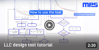
How to use the tool
-
Define operation boundaries of the converter. Maximum and minimum input and output voltage. From specification it will calculate turn ratio of the transformer (n) and the maximum and minimum gain of the resonant tank (Mg). The Maximum Obtainable Peak will be calculated with the Maximum Peak Gain graphic.
-
Considering Maxium peak gain, choose a value for quality factor (Q) and Normalized inductor(Ln). Q is the quality factor of the filter created with Lr and Cr, and Ln (Ln=Lm/Lr) is the ratio between the resonant inductance (Lr) and the transformer's magnetizing inductance (Lm).
- Ln adjusting: When reducing the value of Ln the maximum peak will increase, but as a counterpart the value of Lm will also be reduced. This will facilitate the achievement of the ZVS condition, but can also introduce a higher ripple in the input current, so higher conduction losses.
- Q adjusting: The higher the value, the narrower the bandwidth and also the lower the gain. As a general consideration, as we increase the value of Q, the same increase in switching frequency leads to a greater gain variation. This is bad behavior for a stable response. So the lower the Q the more stable the system.
- The user must select a value greater than the red line (Mgmax) that represents the minimum gain your system needs. From the chosen value, the MPS tool will calculate the resonant inductor value (Lr) ad capacitor value (Cr).
- Next step is to visualize whether the selected Ln and Q can achieve the expected behavior or not, and also to define an operation window for the controller. The user must check whether the maximum gain is achievable on the overload curve within the inductive region. The Gain Response gaph gives different situation (Ioutmax, Voutmax, Ioutmin, Voutmin) depending on the calculated Q. The Q is inverse to equivalent resistance (Vo / Io)
- Choose normalized frequency window by moving the slider, considering following design constraints:
- Converter must act in the inductive region (fn > 1; fs > fr) so switching frequency must be above the resonant frequency of the LC-tank.
- The closer the switching frequency is to the resonance frequency, the better the efficiency.(fn = 1).
- The lower the resonance frequency, the more voluminous the components
- The gain of the lower frequency (fn min) is slightly higher than the maximum gain point. (Mgmax)
- By defining the frequency Window the tool will give the minium and maxiumum switching frequency.
Glossary
| Ln | Normalized Inductance |
| Lm | Magnetizing Inductance |
| Lr | Resonance Inductor |
| Q | Nominal Quality Factor |
| Cr | Resonance Capacitor |
| MG | Gain |
| Fn | Normalized Frequency |
| Fsw | Switching Frequency |
| Fo | Resonance Frequency |
Flow Chart


Specifications
Define your input and output circuit specifications:
Input
Output
Maximum Peak Gain
Choose, by clicking in the graph, a combination of Ln and Q (a point) above the Mgmax limit (red line).
Follow the guidelines described at the "How to use the tool" section (point 2) to select the optimum values for each application.
Less Commutation losses
Less Conduction losses
Better Efficiency
Easy to stabilize
Suggested n =
Qmin (10% Load) = | Qmax (Over Load) =
Gain Response
Choose a normalized frequency range, in where the converter will operate, by moving the slider. The gain response can be adjusted by changing Lr and Cr.
Notice that by doing so the Resonance Frequency and Nominal Quality Factor will change.
Final Results
| Frequency Range | |
|---|---|
| fsmin | fsmax |
| RMS Current Values | |
|---|---|
| Primary | Secondary |
Nxp Resonant Smps Design Tool
Source: https://www.monolithicpower.com/en/design-tools/design-tools/llc-design-tool.html
Posted by: smithbelve1956.blogspot.com
0 Response to "Nxp Resonant Smps Design Tool"
Post a Comment